MIL-T-13291F
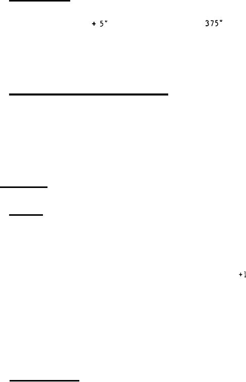
3.5.2 Class B and C. Class B and class C tanks with dip compartment capa-
cities up to 10 cubic feet, when filled to 80 percent of capacity with a heat
transfer fluid shall be capable of raising the temperature of the fluid, with
F to not less than
F in not more than 4
the cover closed, from 70
hours, and tanks with capacities from 10 to 20 cubic feet in not more than 5
hours.
The fluid used for the heating requirements shall have an average
Heating requirements of
specific heat content of not less than 0.50 BTU/lb.
tanks with dipping compartment capacities greater than 20 cubic feet shall be
as specified (see 6.2.1).
3.5.3 Operating controls and indicators. Operation of the hot-dip tank
shall be controlled by a master switch, a programming switch, and a thermosta-
tic switch.
The thermostatic switch shall be of the indicating type or a
thermometer shall be provided to indicate the temperature of the dip material.
Indirectly heated tanks shall be provided with thermometer to indicate tem-
perature of the heat transfer fluid. Two indicating lights shall be provided.
One light shall function when the programmer has made current available to the
thermostat and the other light shall function when current is being supplied
to the heating units.
3.6 Components. The hot-dip tank shall consist of, but not be limited to,
the following principle components.
3.6.1 Cabinet. The cabinet shall be a welded fabrication of sheet steel
and shall rigidly support all component parts and a load in the dip compart-
ment of not less than 125 pounds per cubic foot of dip compartment capacity.
Unless otherwise specified (see 6.2.1), the cabinet shall have not less than 4
legs with bearing plates drilled for floor mounting, or have base supports to
Supports shall be
raise the tank not less than 3 inches above the floor.
Unless otherwise
located crosswise and not greater than 40 inches apart.
specified (see 6.2.1), the dip compartment top shall be 36
inch above floor
level except for tanks requiring greater height for reason of capacity
The cabinet construction shall be free of obstructions to the
requirements.
work area above the dip compartment.
Controls and indicators shall be
grouped, readily accessible for adjustment and maintenance, guarded to prevent
Cabinet construction
contact with the dip material, and securely attached.
shall prevent contact between insulation and dip material. The cabinet shall
provide access for inspection and replacement of heating units. A steel shelf
or shield shall be provided above the controls and electrical equipment to
provide protection for oils and waxes.
3.6.2 Dip compartment, The dip compartment of tanks with capacities up to
5 cubic feet shall be fabricated of sheet steel not less than 12 gauge, from 5
to 10 cubic feet not less than 10 gauge, and tanks with capacities greater
Temperature
than 10 cubic feet not less than 3/16-inch thick sheet steel.
sensing elements of controls and indicators shall be recessed in the dip com-
partment side or bottom. There shall be no obstructions within the dip com-
A drain shall be provided in the lowest part of the dip compart-
partment.
ment. The drain for tanks up to 5 cubic feet shall be not less than 3/4 inch,
7
For Parts Inquires call Parts Hangar, Inc (727) 493-0744
© Copyright 2015 Integrated Publishing, Inc.
A Service Disabled Veteran Owned Small Business